
Engineering Guide to Mining Belt Conveyor Pulley Calculations
Overview of Conveyor Pulley Functions
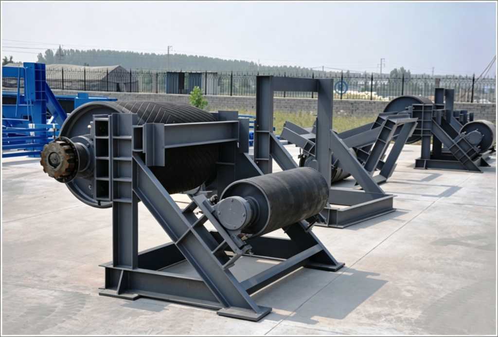
Conveyor pulleys are fundamental operational components within a belt conveyor system. Depending on their location and system integration, they perform critical operations including driving the belt, maintaining structural belt tension, and altering the linear direction of the conveyor belt.
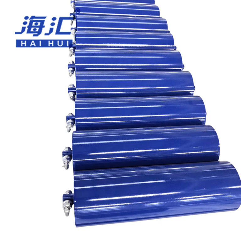
These components are broadly categorized into driving pulleys, tensioning pulleys, motorized pulleys, bend pulleys, and snub pulleys. To prevent operational hazards and optimize performance, the surface or “shell” of a pulley is configured with one of three primary finishes:
- Smooth Steel (Bare) Finish: Applied primarily in low-power systems operating within dry, controlled environments with minimal moisture.
- Rubber Lagging Finish: Used in damp or wet environments where high power transmission is necessary. This finish prevents belt slippage by providing a high coefficient of friction.
- Cast Rubber Finish: Provides maximum durability and slip resistance under heavy-duty operations.
Technical Classifications and System Construction
Conveyor pulleys are engineered to match specific functional zones along the conveyor loop. The primary industrial types are detailed below:
1. Motorized Pulleys (Electric Drums)
A motorized pulley integrates the electric motor, high-speed mechanical gear reducer, and the drive pulley shell into a single, sealed enclosure. This space-saving design acts simultaneously as the power source and a directional roller for the conveyor belt.
Due to its fully enclosed internal layout, the assembly features a compact structure, low total weight, high sealing performance, and simplified installation routines.
2. Standard Driving Pulleys
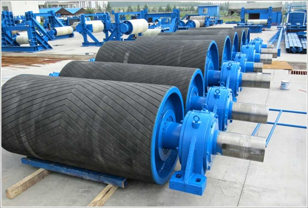
The driving pulley is the primary component that transfers mechanical torque from the motor drive system to the moving conveyor belt. To prevent slippage, these pulleys feature a cast rubber or polyurethane lagging layer machined with specialized groove patterns, which assist in discharging dirt, water, and loose material.
3. Bend and Snub Pulleys
- Bend Pulleys: These units redirect the return belt loop to form a continuous closed circuit, frequently serving as the tail pulley or integrating directly into gravity take-up tension systems. Pulleys contacting the non-working clean side of the belt often utilize smooth rubber lagging. Because rubber is flexible and has low thermal conductivity, it prevents wet coal or ore from freezing onto the shell in winter, reducing belt tracking errors and structural wear.
- Snub Pulleys: These are identical in structure to bend pulleys but feature a smaller diameter. They are installed close to the driving pulley to mechanically increase the contact wrap angle.
4. Specialized Slag-Discharge Pulleys
Designed specifically for material handling systems prone to debris accumulation. The pulley shell features parallel axial slots.
When stray bulk materials enter the return belt path and reach the pulley interface, they fall through these axial slots into the interior of the drum. The inside of the pulley contains a dual-cone structure that is wider in the center and tapers toward the ends. Internal material slides along these conical surfaces and exits through discharge ports at the pulley ends, preventing debris from crushing the belt.
5. Magnetic Pulleys
Magnetic pulleys feature an integrated permanent or electromagnetic core. They are utilized to separate magnetic iron ores from waste rock after crushing, remove iron contaminants from ceramic clay processing lines, and extract iron fragments from coal or foundry sand to shield downstream equipment.
Comparative Pulley Matrix
The following matrix summarizes the operational applications, surface finishes, and core characteristics of standard industrial pulleys:
| Pulley Type | Primary Operational Application | Standard Surface Finishes | Core Technical Characteristics |
| Motorized Pulley | Compact, space-constrained driving zones | Bare Steel / Rubber Lagged | Enclosed motor and gearbox; high sealing rating. |
| Driving Pulley | Primary power transmission and torque delivery | Herringbone or Diamond Lagging | High driving capacity; directional installation parameters. |
| Bend Pulley | Directional redirection; take-up assemblies | Bare Steel / Smooth Rubber | Prevents material buildup; stabilizes belt tracking. |
| Snub Pulley | Wrap angle optimization near drive drums | Bare Steel / Smooth Rubber | Smaller relative diameter; increases friction capability. |
| Slag-Discharge | Debris-heavy processing environments | Slotted Axial Steel Shell | Internal dual-cone layout; self-clearing execution. |
| Magnetic Pulley | Material sorting and tramp iron removal | Bare Stainless Steel Shell | Integrated magnetic field; automatic ore separation. |
Technical Design Principles and Anti-Slippage Criteria
For a belt conveyor to function reliably, the mechanical driving force must overcome the structural resistance of the loop through interface friction. If this friction is insufficient, the driving pulley rotates inside a stationary belt, causing severe thermal friction wear or system fires.
To completely eliminate slippage, the system design must satisfy the fundamental Euler friction relationship:
$$F_{max} \le F_2 \cdot e^{\mu\theta}$$
Where:
- $F_{max}$ = Maximum tight-side belt tension before slippage occurs ($\text{N}$)
- $F_2$ = Loose-side slack tension provided by the take-up system ($\text{N}$)
- $e$ = Base of natural logarithms ($\approx 2.718$)
- $\mu$ = Coefficient of friction between the pulley shell lagging and the belt substrate (dimensionless)
- $\theta$ = Contact wrap angle of the belt around the driving pulley ($\text{rad}$)
To maintain a safe operating margin, engineers must optimize three specific design parameters:
1. Optimization of Contact Wrap Angle ($\theta$)
Where layout constraints limit driving friction, snub pulleys are positioned to increase the belt contact wrap angle around the driving pulley. The standard required wrap angle for industrial driving applications ranges between $200^\circ \text{ and } 240^\circ$ ($3.49 \text{ to } 4.19 \text{ rad}$).
2. Selection of Friction Coefficient ($\mu$)
The choice of pulley surface finish directly dictates the available traction force. The table below outlines standard industrial design friction coefficients under varying environmental conditions:
| Pulley Surface Condition | Operating Environment Humidity | Friction Coefficient (μ) |
| Smooth Steel (Bare) | Clean, dry environments | $0.20 \text{ to } 0.25$ [15] |
| Rubber Lagged / Cast Rubber | Wet, damp, or high-load zones | $0.25 \text{ to } 0.40$ [15] |
3. Structural Orientation of Chevron Grooves
Chevron or herringbone grooved lagging features a distinct operational direction and is restricted to single-direction conveyors.
During installation, the chevron point must point in the same direction as the belt travels. This orientation creates an outward axial force component along the pulley face, which tensions the belt outward toward the edges and forces mud, dust, and water out through the grooves.
If installed backward, the resulting forces push debris toward the center axis of the belt, causing a hollow clearance gap under the belt center line that reduces traction and causes tracking errors. For reversing conveyors, diamond-patterned lagging must be used instead.
Technical Engineering Formulas and Calculations
When determining pulley load distribution and traction limits, engineers use empirical relationships to size the minimum slack-side tension required to transmit power without slippage.
1. Transmissible Driving Force (Euler’s Relationship)
The net driving force ($F_U$) that a pulley can transmit to the belt is defined by the tension differential between the tight and slack sides:
$$F_U = F_1 – F_2$$
To ensure slip-free operation under maximum motor torque, the minimum required slack-side tension ($F_{2,min}$) is calculated using the following formula:
$$F_{2,min} \ge F_U \cdot \frac{1}{e^{\mu\theta} – 1}$$
Where:
- $F_{2,min}$ = Minimum structural slack-side tension required ($\text{N}$)
- $F_U$ = Net peripheral driving force required to move the load ($\text{N}$)
- $\mu$ = Friction coefficient based on pulley lagging choice (e.g., $0.35$ for standard wet rubber)
- $\theta$ = Total wrap angle ($\text{rad}$)
2. Resultant Pulley Shaft Load Calculation
The total vector force ($F_R$) acting on the pulley shaft and bearing housings due to belt tension is determined using the geometric wrap relationship:
$$F_R = \sqrt{F_1^2 + F_2^2 + 2F_1F_2\cos(\pi – \theta)}$$
For simplified radial layouts where tight and slack tensions are approximately parallel (such as a standard $180^\circ$ tail bend configuration), this relationship simplifies to:
$$F_R \approx F_1 + F_2$$
Where:
- $F_R$ = Total resultant radial force acting on the pulley assembly ($\text{N}$)
- $F_1$ = Tight-side incoming belt tension ($\text{N}$)
- $F_2$ = Slack-side outgoing belt tension ($\text{N}$)
- $\theta$ = Pulley wrap angle ($\text{rad}$)
References and Data Sources
- [1] Mechanical Engineers’ Handbook, Friction Coefficients and Design Criteria for Bulk Material Handling Machinery Assemblies, Industrial Systems Press.



 English
 العربية
 Português do Brasil
 Русский
 Español